
Pressure Distribution in Venturi & Nozzle Apparatus Manufacturer,Supplier and Exporter in India
Product Code : SCL-CELE-14137
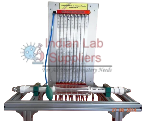
This apparatus is an essential bench-top unit for Fluid Mechanics and
Hydraulics laboratories, designed to experimentally measure the variation of
static pressure and flow velocity in pipe flow using a venturi and a nozzle.
The core principle demonstrated is Bernoulli’s Theorem. This theorem
states that for a steady, inviscid, and incompressible fluid flow along a
horizontal streamline, the sum of the pressure head and velocity head remains
constant.
II. Apparatus Description
The unit consists of a transparent venturi tube and a transparent
nozzle, both mounted horizontally within a pipeline. The transparent acrylic
construction allows for clear visual observation of the flow.
- Pressure
Measurement
- Static
pressure variation is measured using wall pressure tappings located along
the converging and diverging sections of the venturi and nozzle.
- Total
head is measured using Pitot probes positioned along the centerline of
the venturi and nozzle at key locations.
- Instrumentation
- Static
and total pressures are measured simultaneously using an 8-tube
multi-tube manometer. The manometer includes a manifold with an air bleed
valve and can be pressurized using a hand pump.
- A
flow meter is integrated to measure the volume flow rate.
- Operation
- Water
is supplied via a hose connection at the inlet, typically from a standard
Hydraulic Bench. The flow rate is controlled by a valve at the outlet.
- Construction
- The
complete unit is manufactured from corrosion-resistant materials for long
service life.
III. Laboratory Experiments
This apparatus is designed to facilitate hands-on learning and practical
verification of fluid mechanics fundamentals.
Key Learning Objectives
- Demonstrate
and verify the Continuity Equation and Bernoulli’s Theorem.
- Determine
the Coefficient of Discharge Cd for the venturi and nozzle for their use
as flow measurement devices.
List of Experiments
- Familiarization
with static and total pressure measurements.
- Demonstration
of the continuity equation.
- Demonstration
of Bernoulli’s theorem.
- Measurement
of static pressure variation along the venturi and nozzle at different
flow rates.
- Study
of flow velocity variation along the venturi and nozzle.
- Determination
of the Hydraulic Gradient Line and the Energy Gradient Line.
- Determination
of the coefficient of discharge of the venturi and nozzle.
- Study
of the venturi and nozzle as flow measurement devices.
Measurements Taken
- Static
pressures along the venturi.
- Total
pressures along the venturi.
- Volume
flow rate (from the Hydraulic Bench or the integrated flow meter).
IV. Technical Specifications
|
Component |
Feature or Specification |
Detail |
|
Venturi |
Material |
Transparent, Clear Acrylic |
|
Throat Diameter |
12.0 mm |
|
|
Maximum Diameter |
25 mm |
|
|
Upstream Taper |
15 degrees |
|
|
Downstream Taper |
6 degrees |
|
|
Static Pressure Taps |
7 |
|
|
Pitot Probes |
7 |
|
|
Nozzle |
Material |
Transparent, Clear Acrylic |
|
Throat Diameter |
12.0 mm |
|
|
Maximum Diameter |
25 mm |
|
|
Static Pressure Taps |
4 |
|
|
Pitot Probes |
4 |
|
|
Manometer |
Type |
Multi-tube |
|
Range |
0 to 300 mm water column |
|
|
Number of Tubes |
8 |
|
|
Instrumentation |
Flow Rate Measurement |
Flow meter included |
|
Services Required |
Water Supply |
External (e.g., Hydraulic Bench) |
|
Electrical Supply |
240 V, single-phase, 50 Hz |
|
|
Overall Dimensions |
Height (with Hydraulic Bench) |
1.35 m |
|
Width (with Hydraulic Bench) |
0.75 m |
|
|
Length (with Hydraulic Bench) |
1.4 m |
.png)
.png)
.jpg)
.jpg)
.png)

.png)